Notation and standards
Introduction
This document focuses on notation and standards used with LABUST sensors and vehicles. If you are looking for coding specific standards and practices take a look TBA: HERE.
ADD TOC HERE
Enumeration rules for devices
Thrusters
When enumerating and referring to thrusters in documentation and discussions the following applies:
thrusters are counted from 1
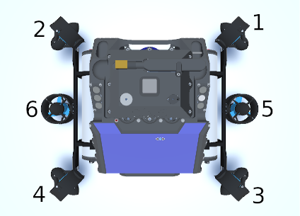
the most fore and most starboard thruster is number 1
thrusters are numbered in increasing order, from starboard to port and from fore to aft
horizontal numbering takes precedence over vertical thruster numbering
A correct enumeration example for a D2 is shown in the figure below.

Note: during programming (Python, C++, etc.) the counting is done from 0 to accommodate the existing vector rules for those languages. However, in any other form of communication the rules above apply.
Doppler velocity logger (DVL) beams
When enumerating beams, the following applies:
beams are counted from 1
the front facing beam is number 1
beams are counted in increasing order, from starboard to port and from fore to aft
TBA: example image.
Thruster control signal standards
Positive thrust
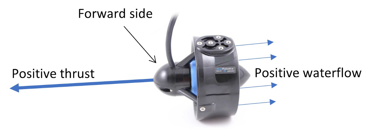
Thrusters often have a preferred direction that can be used to define the concept of forward for the thruster. For symmetrical thrusters the forward direction can be defined based on some other design setting or based on the mounting on the vehicle.

Consider the Blue Robotics T200 thruster example above. The forward direction is easily deduced from the shape of the thruster. The rotation direction of the propeller depends whether it is a counterclockwise or clockwise propeller. Irrespective of the propeller the forward direction is always the same and it coincides with the positive thruster control signal. For the T200 thruster example, the control signal is defined by a pulse width 1100us – 1900us with 1500us defined as neutral position. The 1500us-1900us range can be defined as a positive thruster control signal. Consequently, for these ranges the T200 needs to generate thrust in the forward direction. This directly relates to electric wiring of thrusters and should conform to this standard.
While it is possible to change direction in software but should be avoided when assembling new systems. However, allocation software should support this option for systems where the NGC software is used but rewiring is infeasible.
Thrust normalization in software
Now that a generic thrust direction is defined, it is also advantageous to specify normalized values for thruster signals. Normalization will ensure that different thrusters and even different control signals are handled uniformly by the software. Normalization is applied from the firmware level upwards and up to the user interface level. For example, consider again the T200 thruster. On the firmware level you need to manipulate the nonnormalized 1100us-1900us signal. However, the firmware command input should be normalized to [−1,1]. Similarly, the thruster force should be between [−1,1]. Also, the generalized commanded forces, resulting from thrust allocation, should be normalized [−1,1]. This is better captured in the diagram below.

This normalization is motivated by better introspection of system behavior since numbers define a percentage of maximum capabilities. Without normalization these values vary between individual thrusters and different thruster configurations. All algorithms should use normalized control values, but helper/debug variables can show physical SI values (e.g. N) if needed. Conversions from normalized to physical values can occur on the user interface level as well.
Thrust control is normalized based on the minimum/maximum input signal to the thruster controller.
Thrust force is normalized based on the maximum achievable thrust among all mounted thrusters. Ideally, thrusters are identical, and all are normalized equally. Some thrusters may be less efficient and achieve only 90% of maximum. These thrusters are still normalized with the maximum achievable force, hence they might function in a smaller set, e.g. [−0.8,0.9]. Thrust is often asymmetrical resulting in reduced maximum thrust in the reverse direction. This is also normalized with the absolute maximum thrust. For example, some thruster achieves +50N in forward, but -30N in backward, thus making the normalized achievable set [-0.6, 1.0]. Thrusters often operate on battery power hence normalization should be done with maximum battery voltage to ensure values stay within [−1,1] during whole operation range. Storing the force value used for normalization is beneficial and will allow easy calculation of physical values when needed.
Efficiency coefficient relates to thrust force and should be a configurable value in the software. This will allow excluding or fine tuning the actual force generated by the thruster due to occlusions or similar.
Generalized force and torque should also be normalized so that for each degree of freedom the maximum force and torque is within [−1,1]. This requires attention when specifying the allocation matrix. Instead of physical values the matrix needs to have customized values to ensure normalized thrust forces add up to normalized generalized forces/torques. Take this into account when recalculating into physical values for display or analysis.
On normalization of velocities
In theory, velocities could also be normalized, but since the physical magnitude of velocity is “easily grasped” by everyone there is no additional benefit in normalization. In fact, one could argue that normalizing the velocity would induce confusion.
On storing normalization data
Normalization data for each vehicle, including any measurements, should be stored in a single document (e.g. spreadsheet) for easy access and use by everyone. Including this document within the vehicle repository is advisable.
Reference frames
ROS
We follow the official ROS frame definitions found here. Standard way of communicating between nodes is in ENU frame, but some algorithms may use NED frame instead. If NED frame is used, it is noted in the algorithm description.
For vehicles we use FLU frame as default. If algorithm expects ENU frame as input then FLU is the vehicle frame. If algorithm expects NED frame, then FRD is the vehicle frame.
Unity
In Unity we adopted the Unity frame definition and use Z - forward, Y - up and X - right for vehicles and sensors. Unity origin frame acts as a ROS map frame. They have the same origin and follow the ENU standard where Unity Z is North, X is East and Y is Up.